
Part Three: Intermediate Signals
In this part we look at the operation of the signal system as applied to movements between interlockings and how each individual signal will react to different conditions established by the dispatcher.
Generally speaking, signals that govern movements between interlockings are not controlled by the dispatcher. Instead they operate automatically within the CTC system and their aspect determined by train location and track condition. These signals are known as intermediate or automatic signals. These signals can be located on a mast, bridge or cantilever structure and in some rare cases as a dwarf signal. Intermediate signals are defined as “A block signal which conveys Stop and Proceed (Rule 291) as its most restrictive indication.” This indication (Stop and Proceed Rule 291) informs the engineer that he must stop at the red intermediate signal and then he may proceed not exceeding 15 MPH and prepared to stop short of an obstruction, or anything else that may require him to stop. Some railroads changed the old “Stop and Proceed Rule 291” to a Restricted Proceed indication. This new indication was intended to save fuel, studies showed that it took three GP-9’s 40 or more gallons of fuel to accelerate a 12,000 ton train to 40MPH. With this “new indication” trains were not required to stop but instead allowed to simply proceed by the red intermediate signal at restricted speed.
Intermediate signals can be identified by the presence of a number plate which is attached to the mast or in adjacent proximity to the signal. The number assigned to each intermediate signal reflects the subdivision’s mile post in tenths of a mile. In keeping with most railroads practice of numbering eastbound traffic even and westbound traffic odd, the eastward signals take the even mile post number and the westward signals take the odd mile post number to the nearest tenth of a mile.
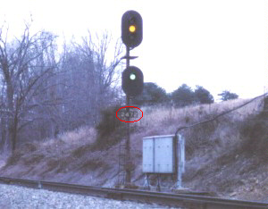
Figure 4 shows a typical layout of intermediate signals between interlockings. Intermediate signals are commonly spaced at one train length apart or approximately two miles. The number of intermediate signals between interlockings is determined by the distance between these locations, the greater the distance the more intermediate signal locations required. This allows for greater flexibility in the operation of the signal systems. For example if the dispatcher has a fleet of westbound trains to run these trains can follow one another at a safe distance apart between interlockings. In this arrangement undue delays to trains are eliminated by allowing following movements, while safety is still maintained by preventing opposing movements between adjacent sidings.
In figure 4 lets assume that all conditions are normal (i.e. no trains are in this territory and no home signals are cleared for a route at interlocking A or B). In this condition all home signals will display Stop (Rule 292), signals 1203 (MP 120.3), 1204 (MP 120.4), 1227 (MP 122.7), and 1228 (MP 122.8) will be dark (i.e. not lit). These signals are normally dark and will light only if a train is occupying the block immediately ahead of the signal. This feature is known as Approach Lighting. Even though these signals are dark the associated circuitry will be as such that if they where lit they would display the following. Signal 1203 and signal 1228 will display an Approach indication (yellow Rule 285). Additionally signals 1204 and 1227 will display a Clear indication (green Rule 281).
Figure #5 shows an intermediate signal location in double track territory. These signals operate much like those in figure 4. A common practice is to light all intermediate signals at this location together for both tracks under the same conditions, regardless of what track is occupied. This is known as “two track approach lighting”. It is important to note that some railroads (C&O, GTW, DT&I, etc.) did not approach light home signals, but instead lit them continually so that their aspects could be seen by maintenance of way employees, giving them advance warning of approaching trains.
The dispatcher will now clear a westward signal ( i.e. signal L14) at interlocking (B) by positioning signal lever number 14 to the L position and pushing the code start button. Signals 1228 and 1204 will now automatically go to red. This ensures that a train does not receive a favorable indication into a block if an opposing route is established. This is called a tumble down, all opposing intermediate signal will tumble to red all the way back to the next interlocking, like a set of dominos. This feature keeps the dispatcher from clearing an eastward signal at interlocking (A) and prevents him from making a “corn field meet.” Additionally all of the intermediate signals between these two interlockings will now light. Once the tumble down is complete signal L14 will display a Clear indication (green over red Rule 281). The dispatcher will now clear signal L6 for the westbound to enter the siding at interlocking (A), after all of the conditions discussed in part two of this series are met signal L6 will display an Restricting indication (red over yellow Rule 290). Signal 1203 will not upgrade in this situation to a Clear indication (green) like one might imagine but instead will remain an Approach indication (yellow). This is because a Restricting signal may require that the engineer stop his train for an obstruction shortly beyond the home signal.
As the westbound train proceeds by each signal it will automatically turn to red. To improve traffic flow, it is desirable to permit trains to follow each other in the same direction at a safe distance apart. To accomplish this the signal system will electrically set a traffic stick. This “traffic stick” will enable the dispatcher to clear signal L14 once again and allow a second westbound to follow one block behind. Signal L14 will now display an Approach indication (yellow over red Rule 285.) This feature also keeps the opposing intermediate signals at red behind the westbound train until the block is clear. Each intermediate location will set this traffic stick and enable the proceeding signal to display an Approach indication. Once the westbound train has progressed and the caboose is no longer occupying the detector track circuit of interlocking (A) all intermediate signals will now return to their normal status. The eastward signals work exactly the same for the eastward direction.