Part Four: Signal Aspects and Indications
Aspects and Indications are the basic building blocks of a signal system. Aspects are the means in which the signal conveys its indication to the train crew, either by one color being displayed or by a combination of colors being displayed. The Indication is the action that the aspect uses to inform the train crew to take, thereby insuring safe operation of their train. These indications give information as to the allowable speed of interlocked turnouts, block conditions, and information as to the next signal to be encountered.
Early on, the Association of American Railroads (AAR), now AREMA or American Railway Engineering and Maintenance-of-way Association, set guidelines for standard use of signal aspects and indications; however, this did not prevent each railroad from creating its own standards for unique situations. Despite the AREMA “standard”, railroad signal aspects soon became as unique as each railroad’s paint schemes, logo, and structures. For modelers this creates quite a challenge. Not only does one model a particular railroad’s motive power and rolling stock, but to model its unique operating practices. Modeling operating practices might include modeling a commonly used locomotive consist, the use of two cabooses on a local freight, and of course the railroad’s signal aspects.
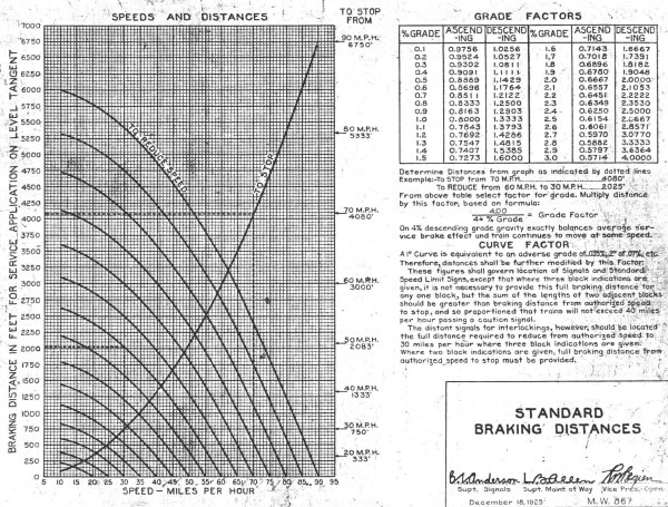
To understand why railway signal aspects go beyond using the simplest two color system of red and green, we must first understand some important train handling factors. A loaded coal train of any where between 90 to 150 cars can weigh 20,000 to 25,000 tons. Depending on grade and track curvature the distances to stop or reduce the speed safely of such trains can vary greatly.

This distance to stop or reduce the speed is referred to as “braking distance”, see figure 6B for standard braking distances. This also explains why some subdivisions have tonnage speed restrictions. These speed restrictions (listed in the timetable) insure that a high tonnage train does not exceed a speed that will prevent stopping within the required distances.
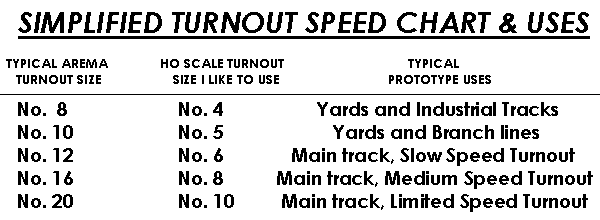
Keeping braking distances in mind, the train crew must have plenty of advance warning of any conditions that will affect the movement of their train. These conditions may be anything from an upcoming stop signal to a switch that the dispatcher has set to crossover from one main track to another or to take a siding. The upcoming turnout may be of many different sizes depending upon the requirements of the physical track layout, typical use, and the philosophy of the chief engineering officer. Locations where turnouts are employed to cross trains over from one main track to another, or to enter single from double track will typically have larger turnouts capable of higher speed movements than those employed to enter a siding or a branch line. The railroad’s objective is to balance cost with efficiency, just as we try to accomplish on our model railroads.
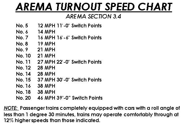
One similarity between model railroading and the prototype is that they both use a numeric system to indicate the size of the turnout. (The NMRA and the AAR established these numbering systems respectively.) Although the prototype turnout numbering system is not the same as the model, the basic principle is. The turnout number is derived from the angle of the turnouts frog, this measurement is referred to as the “frog angle”. The turnout frogs used in modeling are the same as the prototype, and the length of lead and radius of curvature are comparable to scaled-down measurements. In this system the larger the number the less severe the angle of the frog, therefore simple physics tell us that the larger frog angles will accommodate higher speed movements through them on the diverging route than those with smaller frog angles.
Figure 6 shows a chart that I derived for use on my own model railroad. I based this chart on information in the AREMA track standards manual.
With this information one can quickly see why there are so many different signal aspects needed. Not only does the signal need to inform the train crew of approaching block conditions and of the next signal to be encountered, but the speed permitted through a given turnout when set to take the diverging route. To make identification of the signal aspects easier and quicker for the train crew they are given names that corresponds with the action that must be taken. In conjunction with these names, the speed at which the signal is authorizing the train movement is also named.


The following shows some standard signal aspects and indications used on many North American railroads. We will now look at each signal aspect and indication and how and where it would most commonly be used:

CLEAR (Rule 281)
This indication undoubtedly is the engineer’s favorite as it denotes that he has a minimum of two unoccupied blocks ahead of him and all switches within the route govern by the Clear signal are aligned for a non diverging move. With these conditions established, the clear indication allows him to operate at maximum authorized speed. This is sometimes referred to by railroad employees as “track speed”. Maximum authorized speed varies depending on geography track structure. It can vary any where from 40 MPH in mountainous terrain to 60 MPH on level and tangent track. The maximum authorized speed for any given location on a given subdivision is located in the timetable.

APPROACH MEDIUM (RULE 282)
Approach Medium is used several different ways, the most common way it is used, is to inform the engineer that the next signal to be encountered will restrict his movement to medium speed (30 MPH). The next signal will then require the engineer to have the train at a speed not to exceed medium speed – usually a Medium Clear (Rule 283), Medium Approach Medium (Rule 283-A) or a Medium Approach (Rule 286) indication. In this arrangement the engineer has the distance from the Approach Medium indication to the Medium Clear, Medium Approach Medium or Medium Approach indication (i.e. one block length) to reduce the speed from maximum authorized speed to the required medium speed.
Another way the railroad uses the Approach Medium indication is to reduce train speed two blocks in advance of a stop indication (Rule 292). This is used where there is not sufficient braking distance between signals to safely stop the train.

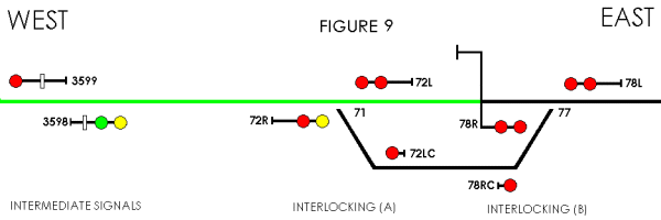
In figure 9 the maximum authorized speed is 40 MPH with a 0.8% descending grade. This requires a braking distance of 1667 feet. Considering that the distance from signal 72R to 78R is only 1287 feet, 380 feet short of the required braking distance, the Approach Medium indication is then employed on intermediate signal 3598. In this application, an approaching eastbound train will start reducing its speed upon receiving the Approach Medium indication. The engineer must now have their train reduced to medium speed at or before reaching the next signal (i.e. signal 72R). Using the exact same mathematical formula as before with the speed reduced from 40 MPH (maximum speed) to 30 MPH (medium speed), the required braking distance is now only 938 feet. This is ample distance for the eastbound train to stop safely at signal 78R.
In a model railroad application, I like to employ the Approach Medium indication to simulate short braking distance if the distance between a particular set of signals is less then one average train length apart. This works quite nicely in the case of a short block where an operator is more likely to miss an Approach indication and run by the next signal displaying “Stop” into the back end of a brass caboose. As we operate our model train across our railroad and encounter multiple “Clear” indications we tend to become complacent and distracted just as the prototype engineers can. This is not surprising considering that one of the most enjoyable things about this hobby is to socialize with our fellow modelers. It is important to note that some railroads would use an Advance Approach Rule 285A (flashing yellow) in lieu of the Approach Medium aspect.

APPROACH LIMITED (RULE 281B)
Approach Limited is used to inform the engineer that the next signal to be encountered will restrict his movement to medium speed (40 MPH). The next signal will then require the engineer to have the train at a speed not to exceed limited speed – usually a Limited Clear (Rule 283A). In this arrangement the engineer has the distance from the Approach Limited indication to the Limited Clear indication (i.e. one block length) to reduce the speed from maximum authorized speed to the required limited speed.

MEDIUM CLEAR (RULE 283)
The Medium Clear indication is used to communicate to the engineer that the dispatcher has set a power operated turnout for the diverging route and that the speed on that route can not exceed medium speed (30MPH). It also indicates a minimum of two unoccupied blocks are ahead of him. The “diverging route” may be to crossover from one main track to another, enters a siding and/or enters double from single track.

Figure 10 shows one common use for the Medium Clear indication. In this illustration the dispatcher has set crossover 9 to the reverse position to cross an eastbound over from track 1 to track 2 at interlocking (B). Signal 10R is displaying the Medium Clear indication in addition signal 2R at interlocking (A) is displaying the Approach Medium indication to advise the eastbound engineer of the upcoming medium speed restriction. Once the last car of the eastbound train clears interlocking (B) the engineer may then resume maximum authorized speed.

LIMITED CLEAR (RULE 281C)
The Limited Clear indication is used to communicate to the engineer that the dispatcher has set a power operated turnout for the diverging route and that the speed on that route can not exceed Limited speed (40MPH). It also indicates a minimum of two unoccupied blocks are ahead of him. The “diverging route” may be to crossover from one main track to another, or to enter double from single track.
MEDIUM APPROACH MEDIUM (283-A)
The Medium Approach Medium indication is used to indicate to the engineer that the dispatcher has set a power operated turnout for the diverging route and that the speed on such route can not exceed medium speed (30 MPH). It also informs them that they must not exceed medium speed approaching the next signal.

Figure 11 shows one common use for the Medium Approach Medium indication. In this illustration the dispatcher has set crossover 9 to the reverse position to cross an westbound over from track 2 to track 1 at interlocking (B) and back over to track 2 at interlocking (A). Signal 12L is displaying the Medium Approach Medium indication. The approaching westbound engineer will proceed through interlocking (B) and over to track 1 not exceeding medium speed. He will then proceed not exceed slow speed approaching the next signal (i.e. signal 2L). The next signal “2L” at interlocking (A) is displaying a Medium Clear indication (Rule 283) to cross the westbound back over to track 2. Our westbound train approaching interlocking (A) is already restricted to medium speed by the previous signal indication received at signal 12L (a Medium Approach Medium indication). This is ample speed to negotiate the medium speed turnout back over to track 2 as indicated by the Medium Clear indication on signal 2L.

APPROACH SLOW (RULE 284)
The Approach Slow indication is used to inform the engineer that the next signal to be encountered will restrict their movement to slow speed (15MPH). The next signal will then require them to have the train at a speed not to exceed slow speed, usually a Slow Clear (Rule 287) or Slow Approach (Rule 288) indication. In this arrangement the engineer has the distance from the Approach Slow indication to the Slow Clear or Slow Approach indication (i.e. one block length) to reduce the speed from maximum authorized speed to the required slow speed.

APPROACH (RULE 285)
This indication denotes that the engineer has only one unoccupied block ahead of them and all switches within the route govern by the Approach signal are aligned for a none diverging movement. With these conditions established, the engineer must begin reduction to medium speed (30 MPH) at or before reaching the Approach indication. In addition to reducing their train to medium speed, he must also take action to be prepared to stop at the next signal they encounter.

MEDIUM APPROACH (RULE 286)
The Medium Approach indication is used to indicate to the engineer that the dispatcher has set a power operated turnout for the diverging route, and that the speed on such route can not exceed medium speed (30MPH). It also indicates that only one unoccupied block is ahead. The “diverging route” may be to crossover from one main track to another, enters a siding and/or enters double from single track. In addition to restricting the movement to medium speed they must also take action to be prepared to stop at the next signal he encounters.

In figure 13 the dispatcher has set crossover 9 to the reverse position to cross an eastbound over from track 1 to track 2 at interlocking (B). Signal 12L is displaying the Medium Approach indication. The westbound engineer will proceed through interlocking (B) and over to track 1 not exceeding medium speed. They will then proceed not to exceed medium speed and prepare to stop at the next signal they encounter (i.e. signal 2L).

SLOW CLEAR (RULE 287)
The Slow Clear indication is used to indicate to the engineer that the dispatcher has set a power operated turnout for the diverging route and that the speed on such route can not exceed slow speed (15MPH). It also indicates a minimum of two unoccupied blocks are ahead. The “diverging route” maybe to crossover from one main track to another or enter a siding.

Figure 12 show one common uses for the Slow Clear indication. In this illustration the dispatcher has set crossover 177 to the reverse position to cross an eastbound over from track 1 to track 2. Signal 178R is displaying the Slow Clear indication, and in addition, intermediate signal 1654-1 is displaying the Approach Slow indication to advise the eastbound engineer of the upcoming slow speed restriction. Once the last car of the eastbound train clears the interlocking the engineer may then resume maximum authorized speed.

SLOW APPROACH (RULE 288)
The Slow Approach indication is used to indicate to the engineer that the dispatcher has set a power operated turnout for the diverging route and that the speed on such route can not exceed slow speed (15MPH). It also indicates that only one unoccupied block is ahead. The “diverging route” may be to crossover from one main track to another, or enter a siding. In addition to restricting their movement to slow speed they must also take action to be prepared to stop at the next signal encountered.

In figure 14 the dispatcher set switch 1 to the reverse position for westbound to enter the mainline from the siding at interlocking (A). Signal 2LB is displaying the Slow Approach indication. The westbound engineer will proceed through interlocking (A) and on to the main track not exceeding slow speed. He will then proceed not exceeding medium speed and prepare to stop at the next signal he encounters (i.e. signal 443 @ MP 44.3).

RESTRICTING (RULE 290)
This indication puts much responsibility on the engineer for the safe movement of their train. As stated in most railroad’s book of rules, the engineer must ” Proceed prepared to stop short of train, obstruction, switch improperly lined, broken rail or anything that may require the speed to be reduced, but not exceeding fifteen (15) MPH.” The statement in this rule “but not exceeding fifteen (15) MPH” is only applicable in the best of conditions. If visibility is low or obstructed, the speed must be reduced below the 15 MPH maximum allowable to permit stopping short of an upcoming obstruction. The Restricting indication can be used a number of ways, such as entering a yard, siding or for “back to train” and/or “call on” movements.

STOP AND PROCEED (RULE 291)
The Stop and Proceed indication can only be displayed by an intermediate signal (signals with number plates). Intermediate signals are defined as “A block signal which conveys Stop and Proceed (Rule 291) as its most restrictive indication.” This indication (Stop and Proceed Rule 291) informs the engineer that they must stop at the red intermediate signal and then proceed, being prepared to stop short of an obstruction, or anything else that may require them to stop but not exceeding fifteen (15) MPH. This allows for greater flexibility and efficiency in the operation of the signal system. For example, if the dispatcher has two eastbound trains to run, one behind the other (less than one block between each other), these two trains can follow one another safely with the second eastbound train receiving a Stop and Proceed indication (versus a Stop and Stay indication). Otherwise we will have a stop and wait until the train clears the block ahead. By allowing this type of following movement, undue delay to the second train is greatly reduced.

STOP (RULE 292)
Little if any explanation is needed about this indication. One important point that should be explained, in accordance with some railroads (SP, WP, AT&SF, etc.) book of rules. A stop indication may have a plate with the letter “A” attached to the mast or in adjacent proximity to the signal.
